Introduction to Arduino
F1
2024-2025
Floor 4 - Physic Lab
Mr. Peter
Outline
Outline

Arduino Exercises
1
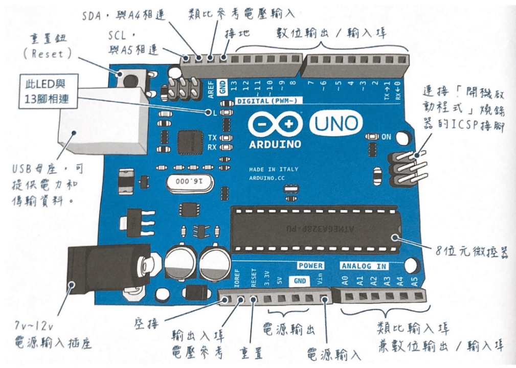
Arduino Structure
Arduino Programming Blocks
void setup() {

}

void loop() {

}
Arduino Programming Blocks
pinMode( pin, mode )Pin Number
- 0 ~ 19 (14 ~ 19 can be represented as A0 ~ A5)
- On Arduino, the pin “~” indicates an analog signal
- LED_BUILTIN (Built-in LED Pin)
Mode
- INPUT
- OUTPUT
- INPUT_PULLUP
digitalWrite( pin, signal )Pin Number
- 0 ~ 19 (14 ~ 19 can be represented as A0 ~ A5)
- On Arduino, the pin “~” indicates an analog signal
- LED_BUILTIN (Built-in LED Pin)
Mode
- HIGH or 1
- LOW or 0
delay( milliseconds )Delay Milliseconds
-
One thousandth of a second
-
Input parameter 1000 represents a delay of one second
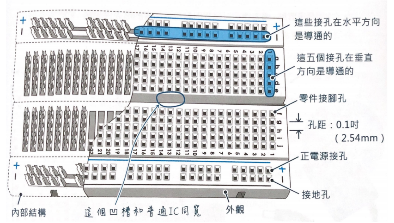
Arduino - white board
Button Control
digitalRead( pin )Pin Number
- 0 ~ 19 (14 ~ 19 can be represented as A0 ~ A5)
- On Arduino, the pin “~” indicates an analog signal
- LED_BUILTIN (Built-in LED Pin).
bool ledState = false;The code above shows how to define a true or false variable in Arduino
delay( milliseconds )To prevent the code within the `loop()` function from repeatedly executing while a button is held down, a `delay()` function can be implemented after the button press is detected.
Ex01 - Gradual LED Fade with Button Control using PWM
-
Controls an LED on pin 5 using PWM (Pulse Width Modulation).
-
A pushbutton connected to pin 2 is used as input.
-
When the button is pressed, the LED gradually brightens.
-
When the button is released, the LED dims down smoothly.
-
Demonstrates:
-
Reading digital input with a pull-up resistor.
-
Controlling LED brightness using
analogWrite(). -
Creating smooth transitions with incremental changes and delays.
-
-
Useful for learning basic input/output and analog effects using digital signals.
Ex02 - Double Press Magic Light
-
Press the button two times quickly (like a double click).
-
If you press fast enough:
-
The LED turns ON for 2 seconds.
-
Then it turns OFF automatically.
-
-
Learn how to:
-
Use a button to control an LED.
-
Detect a double press using simple timing.
-
Use delay() and millis() for time control.
-
Ex03 - Recording and Replaying Button-Driven LED Patterns
-
Use Button A to control an LED:
-
Press and hold to turn the LED on
-
Release to turn it off
-
Each on/off transition and its timing is recorded
-
-
Use Button B to replay the recorded LED pattern:
-
The LED turns on and off with the same timing as recorded
-
-
Demonstrates:
-
Reading digital inputs
-
Detecting input transitions (press/release)
-
Storing time-based events
-
Reproducing time-accurate output behavior
-
-
Useful for understanding:
-
Event-driven programming
-
Timing with
millis() -
Input debouncing and real-time feedback
-
F1 - Arduino Ex05
By Mr Peter


