Introduction to Arduino
F4 ~ F6 ECA
2024-2025
Floor 4 - Physic Lab
Mr Kevin, Mr. Peter
Outline
Outline

Arduino Exercises
1
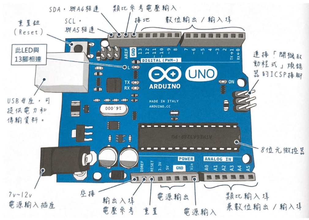
Arduino Structure
Arduino Programming Blocks
void setup() {

}

void loop() {

}
Arduino Programming Blocks
pinMode( pin, mode )Pin Number
- 0 ~ 19 (14 ~ 19 can be represented as A0 ~ A5)
- On Arduino, the pin “~” indicates an analog signal
- LED_BUILTIN (Built-in LED Pin)
Mode
- INPUT
- OUTPUT
- INPUT_PULLUP
digitalWrite( pin, signal )Pin Number
- 0 ~ 19 (14 ~ 19 can be represented as A0 ~ A5)
- On Arduino, the pin “~” indicates an analog signal
- LED_BUILTIN (Built-in LED Pin)
Mode
- HIGH or 1
- LOW or 0
delay( milliseconds )Delay Milliseconds
-
One thousandth of a second
-
Input parameter 1000 represents a delay of one second
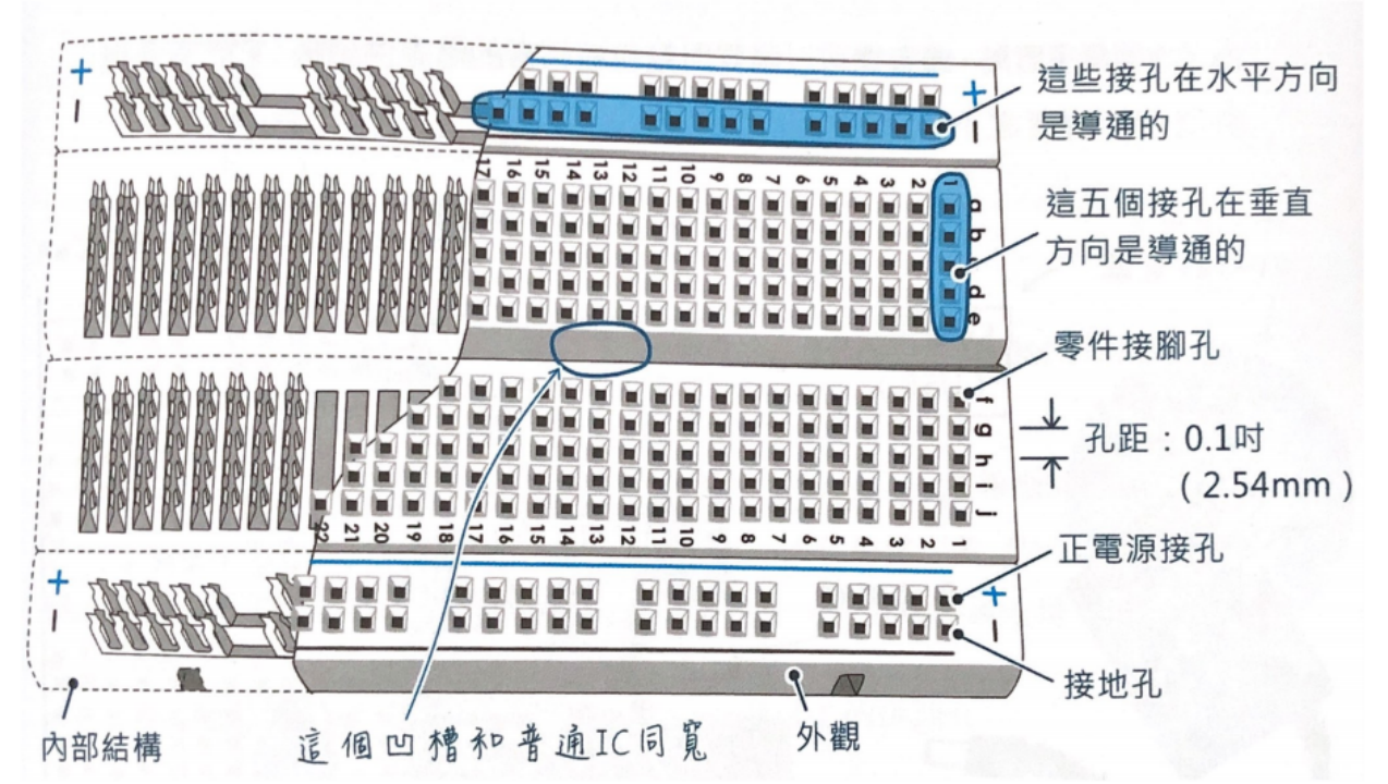
Arduino - white board
Button Control
digitalRead( pin )Pin Number
- 0 ~ 19 (14 ~ 19 can be represented as A0 ~ A5)
- On Arduino, the pin “~” indicates an analog signal
- LED_BUILTIN (Built-in LED Pin).
bool ledState = false;The code above shows how to define a true or false variable in Arduino
delay( milliseconds )To prevent the code within the `loop()` function from repeatedly executing while a button is held down, a `delay()` function can be implemented after the button press is detected.
Ex01 - Multiple LEDs with Single Button Cycle
Goal: Pressing the button cycles through 3 LEDs one by one.
-
Use a counter variable that increments on button press.
-
Reset to 0 after reaching 3.
Ex01 - Multiple LEDs with Single Button Cycle
Goal: Pressing the button cycles through 3 LEDs one by one.
-
Use a counter variable that increments on button press.
-
Reset to 0 after reaching 3.
Ex02 - Multiple LEDs with Single Button
Updated description to reflect the new “ping-pong” sketch
-
Goal: The three LEDs run automatically in a back-and-forth sweep (LED 1 → LED 2 → LED 3 → LED 2 → LED 1 → …), and every button press halves the delay, making the sweep faster.
-
State variables:
-
ledIndexholds the currently lit LED. -
directionis +1 or –1 and determines whether the next step moves forward or backward.
-
-
Edge handling: When
ledIndexreaches either end (0 ornumLEDs − 1), flipdirectionso the sweep reverses direction on the next step.
F4-6 ECA - Arduino Ex04
By Mr Peter


